Nupro Corporation – Process Tech, Slag Detection, and Ladle Stirring

Furnace Slag Detection – SlagView for EAF and BOF

Reliable & Consistent Furnace Tapping

Changes in furnace geometry, operator inconsistency, and different charge weights cause variability in furnace yield and slag carryover. The Nupro Slag Vision furnace tapping system optimizes productivity by guiding the operator through the furnace tapping process.


Proven Technology


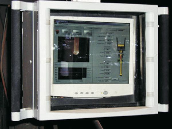
The system incorporates software enhanced near-IR camera images of the tap stream and furnace interior from our ‘aggressive environment’ and ‘extreme environment’ cameras. These images are combined with current and historical process data on a single interface screen to guide the operator to an optimized tap.

Nupro AutoTap HMI screen

Example interface screen showing tap stream image, furnace interior image, ladle filling graphic, furnace angle graphic, and process data analysis.

Typical system components are shown in the following schematic diagram. Additional components may be added as required by the specific application.

Nupro AutoTap system layout

Schematic diagram showing the various components of the SlagVision system. Additional cameras and displays can be specified.


Advanced Image Analysis

The stream is colorized to suit the specific needs of the operators.

Nupro furnace slag detection Nupro furnace slag detection

Slag content of the stream surface  is indicated by red areas in the image. Alarms warns the operator of slag carryover.

At some times during the tap, smoke and fume may obscure the operators view. The operator can use SlagVision for a view of the tap stream from a different angle, sometimes away from the smoke and fume.

SlagVision is an excellent training tool. Through the use of Tap PlayBack, operators can be taught the various types of stream color and morphology to recognize tapping problems early.


Basic System

Our basic economical system includes the following components:

‘Near-IR’ camera and lens in an industrial enclosure.

Industrial image processing unit

Fiber optic signal transmission for noise free images

Basic display software.

Advanced Options

Our advanced options improve the ease of use and help realize additional yield improvements, shorter tap times, and ultimately savings.

Integration to plant systems for automated video & data archiving.

Custom use interface.

Remote screens for melter and operator.

Additional cameras can be added to view the mouth of the furnace.


Slag Vision – Tap Station Display

Tapping information is displayed in the control pulpit and at the tap station pulpit. Custom interface graphics, display locations, and display types can be provided.

BOF

QBOP

EAF


Slag Vision – Aggessive Environment Camera (Nupro AECam-200)

Used for tap stream imaging and ladle viewing, our standard camera housing is built for the steel plant environment with either dry gas or water cooled configurations.

– Aggressive environment camera enclosure, both uninstalled (middle left) and  installed (top right) for a tap stream view.

– Example image (top left) of the normal and software enhanced (inside circle) tap stream view.

– Operator initiated slag carryover (bottom left) at the end of tap; airborne slag is visible with the tap stream left of center.

The Nupro Aggressive Environment camera and housing has been used for imaging the tap stream, furnace lip, ladle interior and tundish pour-box.


Extreme Environment Camera (Nupro EECam-301)

This rugged low maintenance camera and enclosure can be implemented in extreme environments such as:

  1. near the mouth of a vessel
  2. inside an EAF wall
  3. inside a vacuum tank
  4. view of ladle furnace

The standard enclosure is gas cooled (dry instrument quality gas) and suitable for wall mount. The lens tube is variable in length to suit the process requirement. The camera electronics are outside of the process environment and out of harm’s way. The front of the lens assembly has a sapphire window suitable for harsh environment and transmission of wavelengths from visible light to MWIR. There are water-cooling options and retract options available as well. The typical camera assembly is shown below. Process images using this camera assembly are also shown below.

extreme environment process camera assembly
EECam-301 Extreme Environment Camera Assembly
group of three extreme environment process view cameras
Grouping of 3 EECam-301 camera assemblies


extreme environment process view camera in water cooled sleeve
A
extreme environment process view camera inserted into water-cooled panel
B
process view camera mounted into VTD
C

Extreme environment camera with optional water-cooled exterior jacket (A) inserted through water-cooled panel (B) with camera electronics outside of the process vessel (C)


Extreme environment camera used to view QBOP furnace interior during tapping. The tuyeres appear as dark circles in the photograph (top right).

image of steel and slag in ladle

Extreme environment camera view of slag and steel inside a ladle in the secondary processing vessel

Service position

Operating position

For more information, contact us at the phone number or address below.


Nupro Corporation – Process Tech, Slag Detection, and Ladle Stirring